| 일 | 월 | 화 | 수 | 목 | 금 | 토 |
|---|---|---|---|---|---|---|
| 1 | 2 | 3 | 4 | |||
| 5 | 6 | 7 | 8 | 9 | 10 | 11 |
| 12 | 13 | 14 | 15 | 16 | 17 | 18 |
| 19 | 20 | 21 | 22 | 23 | 24 | 25 |
| 26 | 27 | 28 | 29 | 30 |
- BOJ
- 경사하강법
- 9020
- N-Queen
- 재귀
- streamlit
- 밑바닥부터 시작하는 딥러닝
- 4948
- 파이썬
- 그리디 알고리즘
- end to end
- 1101
- REST API
- video retireval
- 파이싼
- 백트래킹
- 손실함수
- 기계학습
- pyenv
- n과 m
- Retrieval
- 오블완
- 1002
- 백준
- 개발환경
- 가상환경
- 티스토리챌린지
- Python
- 신경망 학습
- 15649
- Today
- Total
파이톨치
디지털 시스템 설계 9 latch 본문
Concept Description
| Combinational Circuit | Output depends only on the present inputs. |
| Sequential Circuit | Output depends on present inputs + past inputs (state). |
| Storage Element | A device that can store one bit of information (e.g., latch, flip-flop). |
| Feedback | A technique where the output is fed back to the input to remember a previous state. |
| Clock Signal | A periodic signal that synchronizes state changes in sequential circuits. |

1️⃣ A ______ circuit’s output depends not only on the present inputs but also on the past sequence of inputs.
👉 (Answer: Sequential)

2️⃣ The basic element that stores one bit is called a ______.
👉 (Answer: Latch or Flip-Flop)
3️⃣ The SR latch has two inputs: S (______) and R (______).
👉 (Answer: Set, Reset)
4️⃣ The condition S = 1 and R = 1 in an SR latch is ______.
👉 (Answer: Undefined / Forbidden state / Race condition)
5️⃣ A Level-Sensitive SR Latch changes its state only when the enable signal (C) is ______.
👉 (Answer: 1 / HIGH)
6️⃣ A D Latch ensures that S and R are never both 1 by using an ______ between them.
👉 (Answer: Inverter)
7️⃣ The D Flip-Flop stores data only on the ______ edge of the clock.
👉 (Answer: Rising (0 → 1))
8️⃣ A latch is ______-sensitive, while a flip-flop is ______-triggered.
👉 (Answer: Level, Edge)

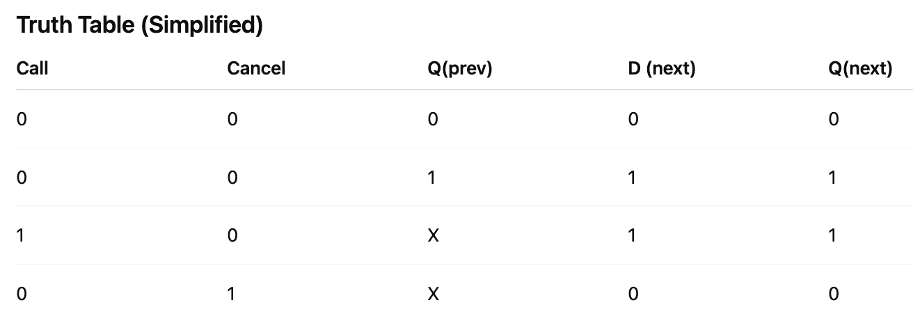
Application Example: Flight Attendant Call Button
Description:
When “Call” is pressed → light turns ON.
When “Cancel” is pressed → light turns OFF.
Light should remain ON even after button is released.

🧩 Exam-Style Concept Fill-in (중간/기말 기출 느낌)
1️⃣ The main problem of an SR latch occurs when S = R = 1, leading to a ______ condition.
→ (Answer: Race)
2️⃣ In a level-sensitive SR latch, the inputs affect the output only when the control input (C) = ______.
→ (Answer: 1)
3️⃣ A D latch can be built from an SR latch by adding a single ______ to ensure R = NOT(S).
→ (Answer: Inverter)
4️⃣ The master-slave D flip-flop uses two D latches connected in series.
The master is active when clock = 0, and the slave is active when clock = ______.
→ (Answer: 1)
5️⃣ A flip-flop stores a value only during the ______ of the clock signal, preventing propagation delay issues.
→ (Answer: Edge (rising or falling))
# Gate => Latch => SR Latch
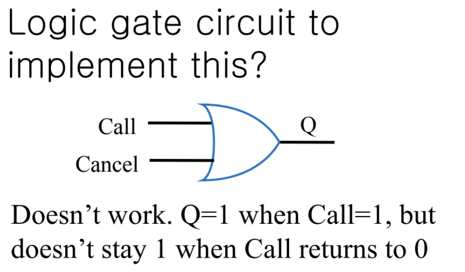


핵심 아이디어: Feedback이란?
“출력(Q)을 다시 입력으로 연결해서, 현재 입력뿐 아니라 이전 출력(과거 상태) 도 회로 동작에 영향을 주게 만드는 것.”
즉, 피드백이 생기면 회로가 ‘상태(state)’를 기억할 수 있게 됨.
→ 이것이 “조합 논리(combinational)”와 “순차 논리(sequential)”의 가장 큰 차이야.
- 이제 Q=1이므로 feedback 입력 t=1
- S를 다시 0으로 내려도, 입력은 (S=0, t=1)이 되어서
Q = 0 OR 1 = 1 그대로 유지됨
👉 즉, 한 번 1이 된 Q는 영원히 1로 잠김(latched)
이게 바로 “자기회귀적 상태 유지” — Memory effect
즉, 이 피드백 구조는 Reset 기능이 없음
한 번 1이 되면 끝임 😅
그래서 이 회로는 “일방향 메모리(one-way latch)” 정도로 볼 수 있어.
“세트는 가능하지만 리셋은 불가능”
그래서 다음 단계에서 등장하는 게 바로 SR Latch (Set-Reset Latch).
이 장면이 바로 방금 봤던 “피드백(Feedback)”의 실패한 OR 회로에서 → “정상적으로 작동하는 저장소(Storage element)”로 진화한 단계야.
이게 바로 SR Latch (Set–Reset Latch), 그리고 여기서 처음으로 정상적인 비트 저장(memory) 개념이 구현돼.
“Does the circuit on the right, with cross-coupled NOR gates, do what we want?”
Yes!
이 회로는 우리가 원하던 “1bit memory”를 구현함.
이게 바로 SR latch야. (S = set, R = reset)

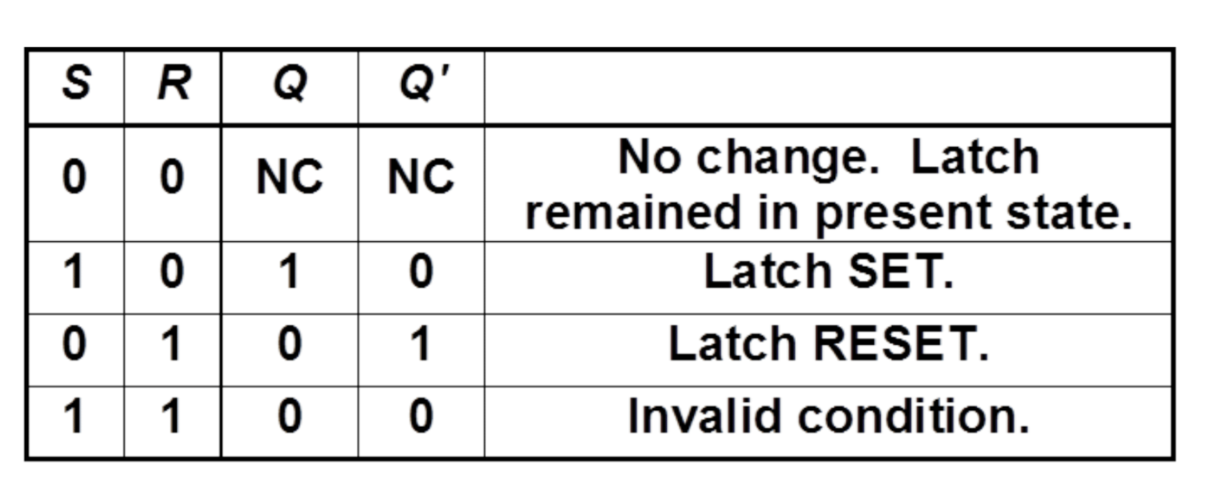
- 이 회로는 **“교차 연결된 NOR 게이트 두 개”**로 구성된 SR 래치다.
- Set, Reset, Hold 세 가지 동작이 가능하고, 피드백 덕분에 과거 상태를 기억함.
- 단, S=R=1이면 두 게이트가 동시에 0으로 출력되며 불안정(경쟁 상태) 발생.
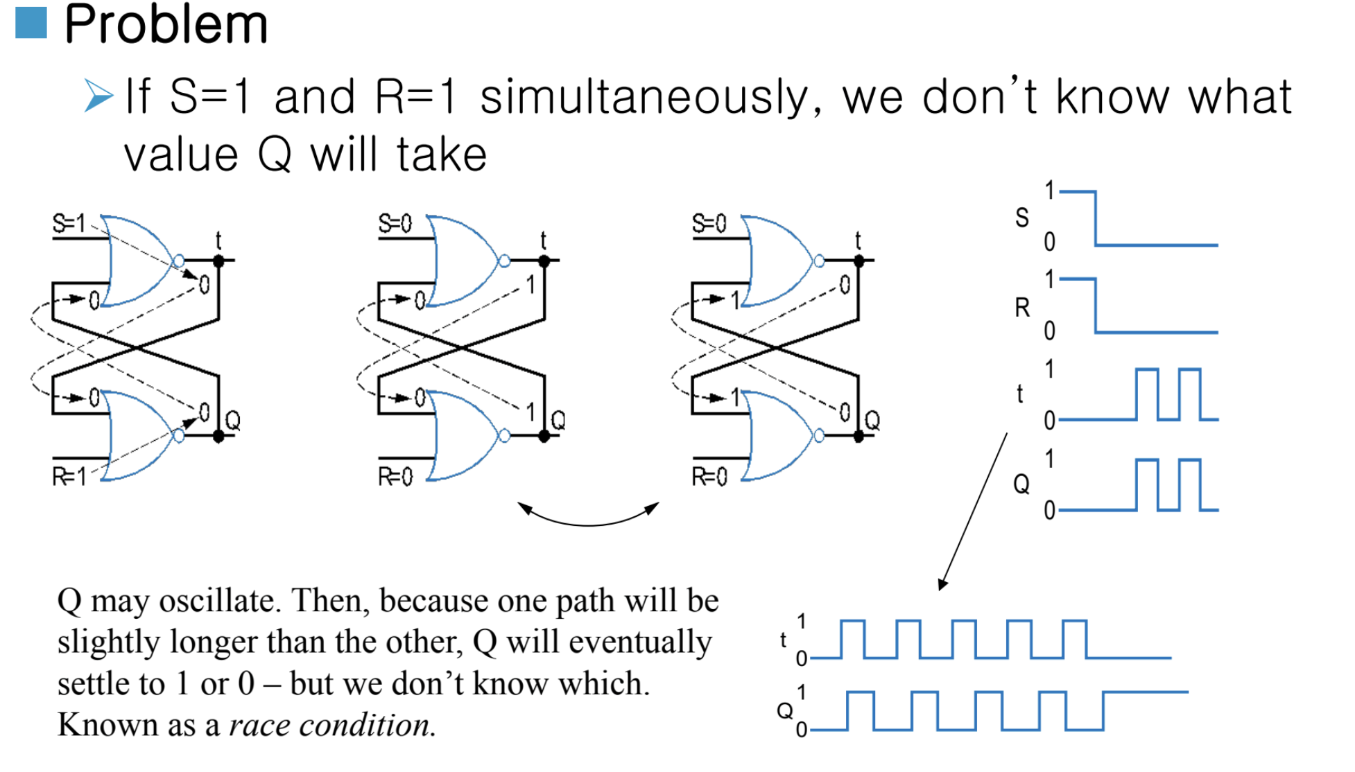
좋아 👌 이 장면은 SR 래치의 유일한 치명적인 문제점을 보여주는 슬라이드야.
앞에서 배운 SR latch(두 개의 교차 NOR 게이트)는 Set과 Reset이 가능했지만, “둘 다 1이 되면 어떻게 될까?” 하는 상황이 바로 여기야.
🎢 즉, 내부에서 일어나는 현상
- Q와 Q̅가 동시에 0이었다가 서로에게 피드백을 주면서
“내가 1이야”, “아니 내가 1이야” 하며
빠르게 번갈아 출력이 변함 (oscillation)
그게 오른쪽 파형에서 보이는 **Q의 미친듯한 진동(불안정 파형)**이야.
이건 실제 회로에서는 수 ns 단위의 진동으로 나타남.
이걸 Race Condition이라고 부르는 이유는: “두 신호가 동시에 0에서 다시 바뀌는 ‘속도 경쟁(race)’을 벌이기 때문”
결국 한쪽 게이트가 미세하게 더 빠르면
Q가 1로 안정될 수도 있고,
다른 쪽이 빠르면 Q가 0으로 안정될 수도 있어.
✅ 즉, “결과가 완전히 비결정적(indeterminate)”임.
💬 파형 분석 (오른쪽 그래프)
- S와 R이 모두 HIGH(1)일 때 → Q는 불안정하게 “고속 진동(oscillation)”
- S, R이 LOW로 내려가면 → Q는 어느 한 값으로 안정되긴 하지만, 예측 불가능
그래서 실험적으로 보면 Q가 0일 수도 있고 1일 수도 있음 —
완전히 운에 따라 달라지는 상태.